The popularity of ultrasound inspection for maintenance and reliability managers is attributed to ease of use, versatility and low implementation cost. Once considered a companion to core predictive technologies like vibration analysis and infrared imaging, the emergence of standalone ultrasound inspection programs is more prevalent for reliability departments today.
Ultrasound is now considered a front-line defense system in the everyday battle for manufacturing uptime. Airborne ultrasound is predictive maintenance for the masses.
Mass Appeal
The applications in which ultrasonic technology can be used are nearly limitless, lending to its mass appeal. Compressed air leak detection, condition-based monitoring of bearings and acoustic lubrication of bearings are popular applications.
Some inspectors monitor thousands of steam traps and pinpoint in-leakage to boilers, condensers and heat exchangers. Others marry ultrasonic inspection and infrared scanning together for added safety to motor control center panel scans or surveys of high-voltage substations and transmission and distribution lines.
Easy to Use
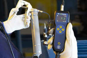
Ultrasound instruments have always been considered user friendly. Being painted this way left consumers with the impression that user-friendliness equated to lacking sophistication.
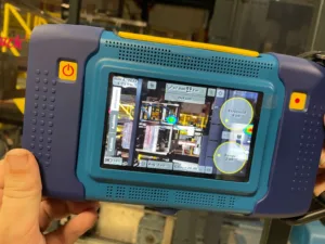
Nothing could be further from the truth for the new generation of instruments. Inspectors can literally design their own instrument to suite their program’s needs and goals, and flexibly change that instrument as their program evolves.

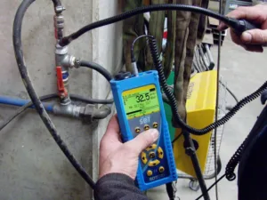
Most detectors work on the basic principle of detecting high-frequency ultrasound and converting it to corresponding audible sounds, which can be listened to with headphones. Additional functions are dependent of the device, but most provide a visual indicator on a bar graph display or a decibel measurement.
Some can even capture a time-specified wave signal that can be analyzed with software. Adding sophistication while maintaining simplicity is a challenge that some manufacturers handle better than others, but the net effect is driving the popularity of this technology to mainstream predictive maintenance (PdM) practitioners.
Ultrasonic analysis offers benefits for all areas of the manufacturing process. Most machine failures could be discovered early, making them treatable issues instead of replaceable downtime issues. Excessive vibration and temperature increases are indicators of mechanical failure on the horizon, but we also learned that microscopic changes in friction forces, detectable early with ultrasound, provide a bigger window of opportunity for scheduled maintenance.
When you hear problems this soon, you are empowered with the ability to limit downtime and overall maintenance cost. Following are some of the most common maintenance applications for airborne ultrasound that can be applied at plants today.
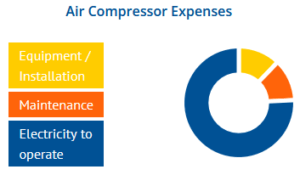
Compressed Air Leak Management

Compressed air is one of the most expensive utilities used in manufacturing. Leaks are expensive and often ignored. While they can be heard with the naked ear, they are difficult to pinpoint because of background noise.
An ultrasonic detector hears leak turbulence through the ambient noise of the factory floor no matter what. The high-frequency component of a leak is directional, making it fast and easy to locate its source.
A compressed air survey with an ultrasonic detector once per quarter will reveal savings potential in the millions and benefit plant managers looking to improve efficiency and reduce costs.
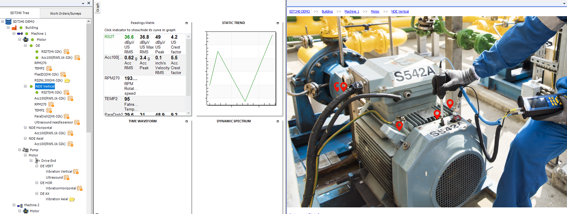
Condition Monitoring
One application that has evolved alongside the new generation of detectors is condition-based monitoring (CBM) of rotating and non-rotating equipment. In both instances, production machines produce frictional forces with high-frequency ultrasonic signatures.
These forces are often masked by ambient plant noise and low-frequency vibrations. Changes in these signatures serve as early indicators of failure and provide comparative information for vibration data.
You want to believe that the majority of your machines are not in an advanced failure condition. Would you rather spend days analyzing gigabytes of data from machines that are not failing or use ultrasound technology to sort the good from the bad so your vibration analysts are focused only on trouble areas? The answer is obvious and reasonable.
Ultrasonic instrument equipped with digital decibel-metering measures and logs the intensity of high-frequency frictional forces. Enhanced detectors also capture time signals alongside the decibel measurement.
Time signals are useful for slow-speed bearing condition assessment, which is one area where vibration analysis struggles.

Condition monitoring with ultrasound provides overall data that is indicative of elevated friction levels from random impacting, rubbing and spalling. These non-sinusoidal events are more interesting to analyze in the time domain, making ultrasonic monitoring useful as a first line of defense instrument.
Collecting information is quick and inexpensive. Much more data can be taken, extending condition monitoring to more machines that may have been overlooked by vibration due to time and costs.
Ultrasonic monitoring will detect a change earlier in the fault cycle than other technologies. For this reason, ultrasound is generally used to alert changes in condition and for a preliminary diagnosis.
Acoustic Condition-Based Lubrication
Over time lubrication breaks down, and the friction forces inherent in any bearing increase. Ultrasonic systems that measure decibel-microvolt levels monitor and predict the relevant need for regreasing of the bearing.
When a baseline ultrasonic alarm is compromised, a lubricator is alerted to the problem and can correct it before the bearing is physically damaged.

Condition-based lubrication monitoring advises lube techs when grease is needed and warns them when too much grease is added. One problem with adding too much grease is compromised seals. For electric motor bearings, this means grease pushed through the seal and into the windings.
One U.S. paper mill decided to stop greasing motor bearings altogether since it was cheaper to replace the bearing instead of cleaning out piles of grease from the motor. This technique has become the norm for establishing lubrication requirements on most production machinery.
Electrical Applications
The versatility of ultrasonic inspections extends to the electrical maintenance department where routine scans of switch gear, substations and high kilovolt transmission and distribution lines are commonplace. There is mounting concern about safety, specifically the danger of arc flash.
Prior to opening high and medium voltage electric panels, inspectors use ultrasound detection to listen to the levels of ultrasound inside the cabinet. The importance of finding problems at an ultrasonic level can’t be overemphasized.

Radio and TV interference are common complaints from local cable companies. Often the source can be traced to a faulty transformer or a failed lightning arrestor.
Pinpointing the culprit is quick and simple with an ultrasonic scan. The directional nature of ultrasound focused on a parabola reveals problems from a safe distance.
Steam System Inspections
A steam trap is an automatic valve that opens for condensate and non-condensable gases and closes for steam. It is designed to trap and remove water, air and carbon dioxide, which hinder the efficient transfer of steam, corrode system components and cause damaging water hammer.
Ultrasonic surveys of the entire steam system will reveal system leaks, blockages, stuck valves and failed traps. Increasing steam efficiency translates to huge dollar savings and increased product quality. Certain types of traps can benefit from dynamic signal analysis.
When monitoring continuous traps, it can be difficult to discern between live steam from a failed trap and flash steam, which is produced when the reduced pressure of the condensate line causes condensate to regenerate back to steam. Viewing the time signal of suspect traps can help distinguish between flash and live steam.
Pump Cavitation
Cavitation is the result of a pump being asked to do something beyond its specification. Small cavities of air develop behind the vanes. These pockets have a destructive effect on the pump’s internal components. During normal data collection, inspectors use ultrasonic detectors to isolate random cavitation, which can be masked by low-frequency modulations.
By using an ultrasonic detector in contact mode, you can isolate the pump vanes and listen for small air pocket explosions. Place the contact probe on the housing of the pump vane and adjust amplification to filter down shaft noise. With some experience, an operator will quickly be able to identify when pump cavitation is present.
Reciprocating Compressors and Valves
Reciprocating valves give breath to compressors. Worn or dirty valves can’t seat properly. Over time springs weaken, limiting the force necessary to snap open and closed, which causes leakage. Valve condition is monitored with ultrasound inspection and spectral analysis software. The demodulated signal from the detector is fed directly to an analyzer or stored as a wave file. Spectra graphs visualize the compressor valve as it opens and closes, as well as intakes and exhausts.

Visualizing the recorded sound file of a compressor valve can tell you a lot about the condition of the valves and their components. Valves are opened and closed by a spring mechanism, allowing reciprocating compressors to intake and exhaust.
The three distinct events (open, intake or exhaust, and close) all occur at split-second timing that is too fast for the naked ear to process. By viewing the wave file in real time, you can stretch this out to visualize each individual event. Time wave images can also be saved and compared over time to see the evolution of wear.
Heat Exchanger and Condenser Leaks
Tube condensers and heat exchangers cool steam, which condenses back to purified water and is returned to a boiler where it is superheated back to steam. Leaks in the tube allow contaminants in, opening the door for corrosion and reduced operating life. Keeping the water pure is the key to efficiency.

The general method of inspection involves scanning with the instrument a couple feet from the tube sheet. If a noisy area is found, it is noted. However, if you switch to an extended flexible sensor, you can scan tube to tube.
If the sound signal on the digital decibel-microvolt meter or the sound in the headset does not change from tube to tube, a leak is unlikely. This is particularly true of tubes located on the outer edges of the tube sheet, as these tubes are more likely to have noisy steam flowing over their outer diameter surfaces.
If a significant signal change occurs, then a leak is suspected. If the leak is within the tube, the difference will be heard at the tube opening. If the noise level is heard on the tube sheet, block the area to eliminate reflected noise, then place a rubber precision tip with an opening of 1/8 inch on the flexible extended sensor and hold it almost on the tube sheet surface.
Valves and Hydraulic Leaks
Over time small leaks, blockages and bypassing will manifest inside hydraulic systems. The sources of these faults are detectable with ultrasonic inspection. Hydraulic oil will form small bubbles, which pop as they are forced across seals and wipers. With a magnetic or contact sensor placed against the housing, you can set the sensitivity to the maximum level to reveal the tiny explosions.
The signatures from a passing hydraulic valve can be a steady rushing sound or an intermittent gurgle. Comparing similar areas in the system to trace blockages and passing will save hours of visual inspection and tear down time.
Where Do We Go From Here?
Ultrasonic inspection, detection and data collection have been around for more than 35 years but only recently have gained acceptance in predictive maintenance departments. Branded as “ultrasonic leak detection,” this technology has shed its type-cast role to become a versatile, important and dynamic member of the predictive family.
Beware of the technology trap. Buying the latest and greatest gadgets, even the useful ones like ultrasound, will only take you so far. For a successful and long-lasting ultrasound inspection program, be prepared to invest in a program implementation specialist to help you establish your goals, plan for the execution of those goals and institute a means to measure the progress of your program as the benefits start rolling in. Click here to view our available SDT Ultrasound product range.
About the Author
Allan Rienstra is the president of SDT Ultrasound Solutions and co-author of “Hear More: A Guide to Using Ultrasound for Leak Detection and Condition Monitoring.”